Pwm Inverter Circuit
When developing a welding inverter i applied forward inverter with two switches topology.

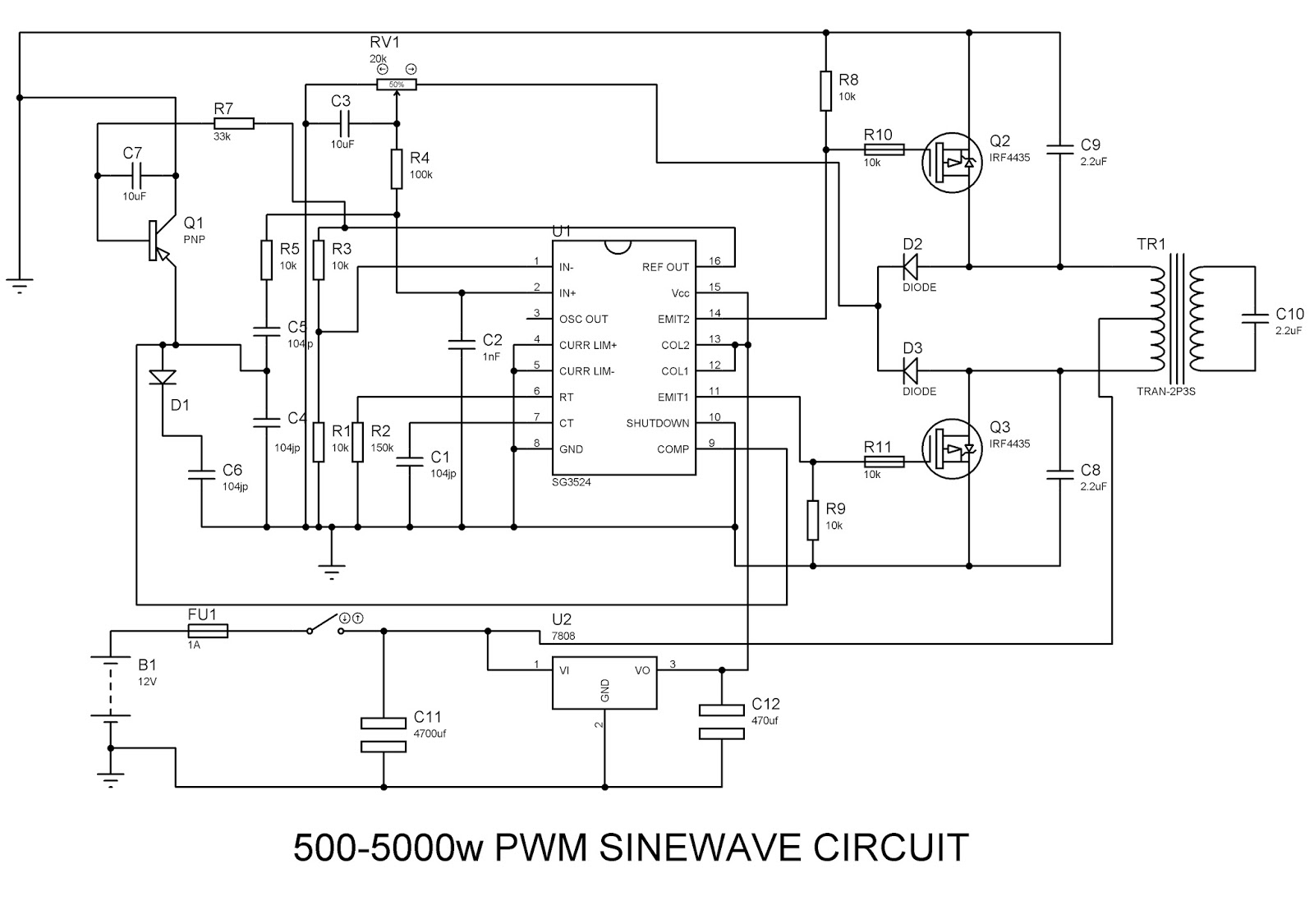
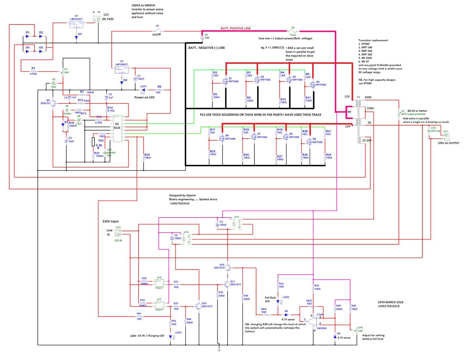
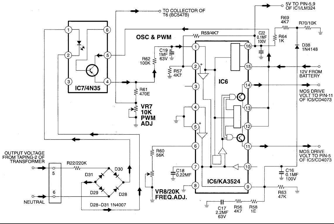
Pwm inverter circuit. Inverters are the device which converts dc direct current to ac alternating current and gives high woltage and current from low power battery source. Simple pwm inverter circuit diagram using pwm chip sg3524 gallery of electronic circuits and projects providing lot of diy circuit diagrams robotics microcontroller projects electronic development tools. Simple low power inverter circuit 12v dc to 230v or 110v ac diagram using cd4047 and irfz44 power mosfet gallery of electronic circuits and projects providing lot of diy circuit diagrams robotics microcontroller projects electronic development tools. Pulse width modulation pwm allows for electronic control over dc motor speed or led brightness.
This articles features schematics and photos of circuits for making pwm without a microcontroller but instead uses a 74ac14 logic inverter chip diodes a capacitor and potentiometer. This is a heavy duty design of a pulse width modulator dcac inverter using the chip sg3524. Ive been using it as a backup to power up all my house when outages occur since aprox. 6 years non stop.
If you like the work and intend to build the circuit dont forget to click on the i made it button. The post discuses the how to make a 3 phase inverter circuit which can be used in conjunction with any ordinary single phase square wave inverter circuit. 100 watt inverter circuit diagram parts list design tips. Inverters are devices that convert dc input supply to ac alternating current.
They are also called power inverters. Using two switch topology.


+Circuit+diagram+using+CD4047+and+IRFZ44+power+MOSFET.png)


