3 Phase Pwm Inverter Circuit
Shrikant view profile 0 files.
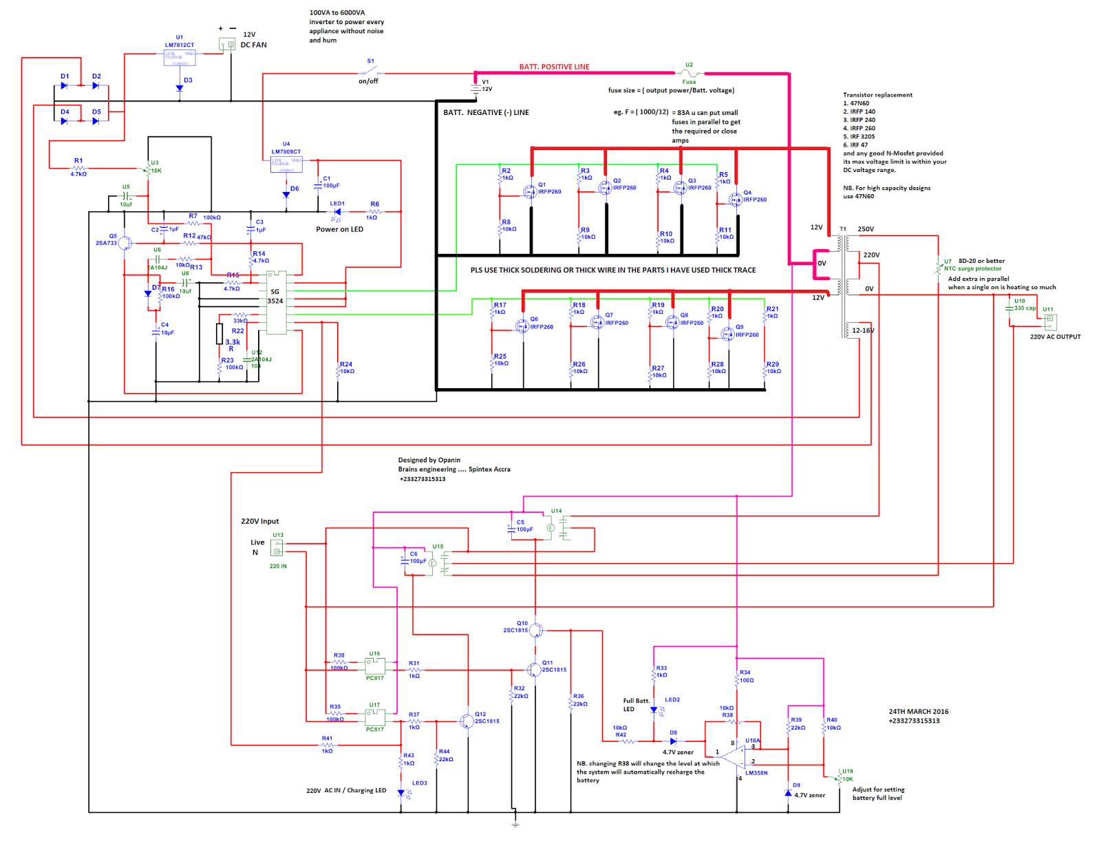
3 phase pwm inverter circuit. With the development of power electronics technology power inverter application has penetrated into all areas generally require a high quality for inverter output waveform. Why 3 phases are with 120 degree phase difference. Circuit diagram program code circuit description generated wave form imagesthe arduino and other. The circuit below shows a 3 phase inverter inverter circuit stage using h bridge mosfets configuration which receives the phase shifted pwms from the above stage and converts them into corresponding high voltage ac outputs for operating the connected 3 phase load normally this would be a 3 phase motor.
As with a single phase inverter pwm may be used to produce a quasi sinusoidal output andor control the output voltage or current. The basic circuit of a three phase inverter. Hello everyone i am trying to create a three phase inverter using pwm as the input to the gate of the mosfets. I am slightly confused by the theory of inverters.
Pulse width modulated inverter model. There are several circuit topologies and control methods used to convert a dc input into a 3 phase ac output. Very easy to follow how an ideal spwm 3 phase inverter generates harmonics.


