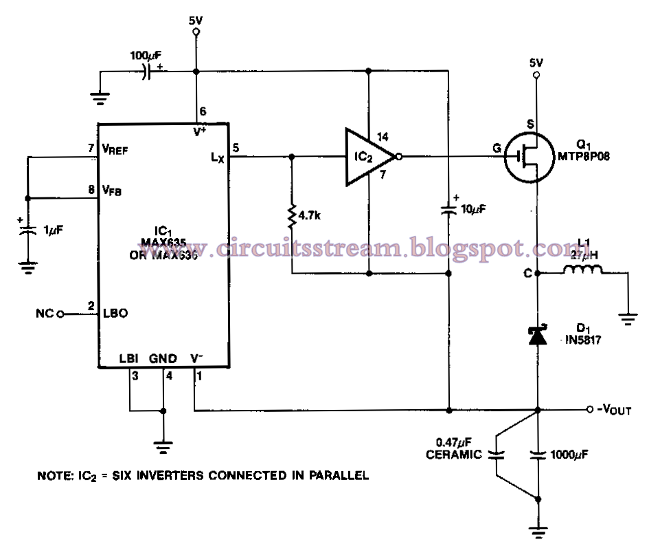
Power Inverter Circuit Diagram
Power supply and power control circuit diagrams circuit schematics.
Power inverter circuit diagram. This is the circuit diagram of 3000w power inverter 12v to 230v modified sinus capable to deliver about 3000w 230v ac output from 12v input. This is the inverter circuit for professional only. A power inverter or inverter is an electronic device or circuitry that changes direct current dc to alternating current ac. The input voltage output voltage and frequency and overall power handling depend on the design of the specific device or circuitry.
Simple low power inverter circuit 12v dc to 230v or 110v ac diagram using cd4047 and irfz44 power mosfet gallery of electronic circuits and projects providing lot of diy circuit diagrams robotics microcontroller projects electronic development tools. 100 watt inverter circuit diagram parts list design tips. Inverters are devices that convert dc input supply to ac alternating current. They are also called power inverters.
Inverter is an electronic device or circuitry that changes direct current dc to alternating current ac. The input voltage output voltage and frequency and overall power handling depend on the design of the specific device or circuitry. This is inverter circuit 500w output. It will convert 12vdc to 220v 50hz.
You can build it easily and inexpensive. Because like working outdoors or to backup storage to use when necessary. Few days ago gohz made a 24v 2000w power inverter in home sharing some design schematics and circuit diagrams. The picture was taken in short circuited.


