Inverter Circuit Diagram 100w
Free electronic circuit diagrams collection.
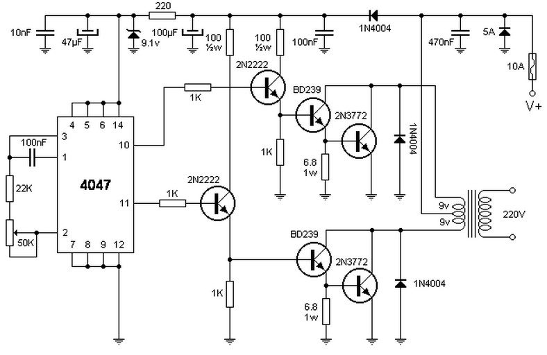
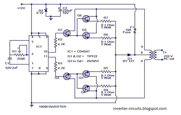
Inverter circuit diagram 100w. Inverter circuits are among the easiest circuits to build for newbies. Here is the circuit diagram of a simple 100 watt inverter using ic. Inverter is an electronic device or circuitry that changes direct current dc to alternating current ac. The input voltage output voltage and frequency and.
The following image is the schematic diagram of 1000w power inverter circuit. The circuit is based rfp50n06 mosfet converting 12vdc battery to become 110v or 220v ac. Simple low power inverter circuit 12v dc to 230v or 110v ac diagram using cd4047 and irfz44 power mosfet gallery of electronic circuits and projects providing lot. This is inverter circuit 500w 12vdc to 220v 50hz.
It easy to make and low cost. Using basic parts transistors 2n3055 ic 4047. Simple pwm inverter circuit using sg3524. This pwm inverter circuit has 12v input 220v output and 250 watt output power.
Output power can be extended. Neon lamp inverter circuit.


.jpg)


